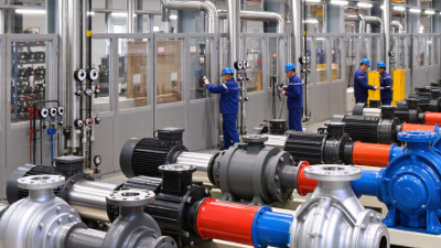
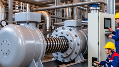
A hydraulic screw pump is a positive-displacement pump designed to move fluid smoothly under pressure. It uses one or more rotating screws inside a close-fitting housing. As the screws turn, their helical cavities capture hydraulic oil and carry it from the inlet toward the outlet. Pressure develops when the downstream system resists this flow.
Pump authority Igor J. Karassik wrote, “A pump is a machine that imparts energy to a fluid.” That simple statement explains the hydraulic screw pump’s purpose. Its rotating screws do not merely push oil forward. They transfer mechanical energy into controlled fluid movement. The result is steady flow, low pulsation, and quiet operation when the pump is correctly selected.
The details matter. Clearances must match the fluid’s viscosity, temperature, and cleanliness. A small metal particle can damage the screw surfaces. Excessive pressure can also shorten service life. This is where real engineering judgment matters.
Not every system needs one.
Compared with gear or piston pumps, a hydraulic screw pump often performs well in applications requiring continuous flow and reduced vibration. Marine hydraulics, lubrication circuits, fuel transfer, and industrial machinery commonly use this design. However, efficiency depends on installation quality, inlet conditions, alignment, and maintenance. A technically impressive pump can still fail when the suction line is undersized.
This guide will explain the pump’s internal structure, working cycle, benefits, limitations, and practical selection factors. It will also question common assumptions, because smooth operation alone does not guarantee reliable hydraulic performance.
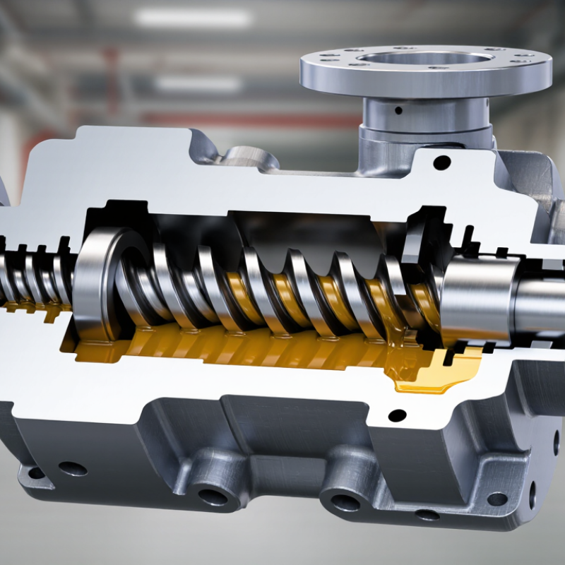
A hydraulic screw pump is a positive-displacement pump that moves liquid through rotating screws inside a close-fitting housing. As the screws turn, they create sealed cavities at the suction side. These cavities carry fluid steadily toward the discharge port. Pressure does not come from the screw alone. It develops when the downstream system resists flow.
The operating principle is simple, but real installations are less forgiving. Screw geometry controls flow rate, while speed affects capacity and shear. Clearances must remain small enough to limit internal slip. Excessive wear can let liquid flow backward between the screw and casing. That reduces efficiency, especially with thin fluids. Viscous liquids usually improve sealing, but they also increase starting torque. Suction piping must stay short, flooded, and free from air leaks. Air is a quiet problem.
U.S. Department of Energy pumping-system guidance reports that pumping systems can consume 25–50% of industrial facility electricity. This figure explains why screw-pump selection deserves more than a catalog comparison. Hydraulic Institute guidance also stresses evaluating viscosity, speed, pressure, and operating point together. A pump may meet its rated flow yet perform poorly in the field. I would question any selection based only on maximum pressure. Actual fluid temperature, contamination, and wear matter more than many early calculations suggest.
A hydraulic screw pump is a positive-displacement machine used to move oil through a hydraulic circuit. Its job is to create steady flow under pressure. The drive shaft turns the screws inside a close-fitting housing. This rotation forms sealed cavities that carry oil from the inlet to the outlet. Flow remains smooth.
The main housing supports the internal parts and controls the oil path. Inside it, intermeshing screw rotors move fluid along their length. One rotor receives torque from the motor or engine. The other rotors follow through their meshing profiles.
Clearances matter greatly. Too much clearance can reduce pressure and efficiency. Too little clearance may increase friction and heat. These small gaps are easy to overlook.
At the inlet, lower pressure draws oil into the screw cavities. At the outlet, the cavities close and push oil into the system. Shaft seals limit leakage around the rotating shaft. Bearings support the screws and maintain alignment during operation. A relief valve protects the pump from excessive pressure. Filters remove particles that could score the screws or damage the seals.
In field inspections, unusual noise often points to air entry, worn bearings, or poor alignment. Yet diagnosis is not always neat. Warm oil can hide early problems, while cold oil can make a healthy pump sound rough. Checking pressure, temperature, vibration, and oil cleanliness together gives a more reliable assessment.
A hydraulic screw pump moves fluid through controlled, rotating cavities rather than forcing it with a reciprocating piston. Inside the housing, two or more helical screws turn with very small clearances. As the screws rotate, fluid enters the suction port and fills the spaces between the screw flights. Those spaces act like sealed pockets.
The pockets travel steadily along the screw length. Their volume changes very little, so the fluid moves smoothly toward the discharge port. The screw threads guide the flow, while the housing prevents most backward leakage. Pressure develops when downstream resistance restricts movement. The pump creates flow; the hydraulic circuit determines the working pressure.
This process explains the pump’s quiet operation and low pulsation. It also shows why installation details matter. Clean oil helps protect the screw surfaces and internal clearances. Air bubbles can cause noise, vibration, and unstable delivery. Excessive viscosity increases starting torque, while low viscosity may increase internal leakage. Real systems are less tidy. Temperature changes can affect both conditions at once.
During field checks, I would inspect the suction line before blaming the pump. A partly blocked inlet can starve the screw cavities and damage them over time. Correct alignment, suitable filtration, and a properly adjusted relief valve support reliable operation. The flow may look simple, but small clearances make contamination surprisingly important.
A hydraulic screw pump uses rotating screws to move fluid through sealed cavities. As the screws turn, fluid enters the suction side and travels steadily toward the outlet. The pump mainly produces flow; system resistance creates pressure. It does not create pressure by magic. A restricted valve, actuator, or narrow passage can raise discharge pressure quickly. A pressure-relief valve protects the circuit when resistance becomes excessive.
Flow control depends heavily on shaft speed. Increasing speed usually increases flow, while reducing speed lowers it with less energy loss than constant throttling. However, real results vary. Fluid viscosity, temperature, and internal clearance affect delivery. Cold oil may move slowly, while overheated oil can leak across worn clearances. Operators should check pressure gauges, flow readings, and fluid temperature together. One reading rarely explains the whole system.
Efficiency includes volumetric and mechanical performance. Good suction conditions reduce noise, vibration, and cavitation risk. Clean fluid also protects the screw surfaces and bearings. From practical maintenance experience, small wear can remain unnoticed until pressure becomes unstable. Efficiency then falls before the pump visibly fails. I would not assume the rated flow is permanent. Seal condition, alignment, and operating speed deserve regular inspection. A slightly lower speed may sometimes deliver better overall efficiency than maximum rotation.
A hydraulic screw pump moves fluid through rotating screws inside a close-fitting housing. Its steady flow creates less pulsation than many other pump designs. This makes it useful where smooth hydraulic performance matters.
Common applications include hydraulic power units, lubrication circuits, marine equipment, and industrial fluid-transfer systems. It can handle certain viscous fluids effectively when temperature and pressure remain within specifications. Operators often value its quiet operation.
A little noise matters. A rising pitch may indicate air intake, worn bearings, poor alignment, or insufficient lubrication. However, not every unusual sound means immediate failure. That assumption can lead to unnecessary repairs.
Maintenance should begin with clean fluid and suitable filtration.
Contamination can damage screw surfaces and reduce internal clearances. Check the inlet line for blockages, loose fittings, and air leaks. Inspect seals for swelling, cracking, or visible leakage. Monitor pressure, temperature, vibration, and motor current during normal operation. Record these readings regularly. Small changes often appear before serious damage.
Confirm shaft alignment after installation or major service work. Misalignment may create heat and uneven wear. Do not operate the pump dry, even briefly. Review the relief-valve setting and follow the equipment manufacturer’s service limits.
In practice, maintenance logs are sometimes incomplete, which weakens fault diagnosis. A simple, consistent record is usually more valuable than a complicated checklist.